20+ autocad gear drawing
Spur gear 20 teeth Module 1. And the table will be automatically filled by the same dimensions in Parameter of Pinion Gear.

10 653 Cad Photos Free Royalty Free Stock Photos From Dreamstime
One way is to get yourself a book that explains the process or look it up on line.
. Geared devices can change the speed torque and direction of a power source. I chose 270 degrees. It is only necessary to create an approximation of the gear tooth form.
Now the note that you have made can be used as a standard note for the other gears drawing. 3D CAD - STP STEP 2D Drawing PDF 2 Drawing DWG QS200-10. Here below are the input data and the corresponding image of the gear created clicking the Run button.
TurboCAD Presentation 2019 Series. 2 Draw a line 120th of the Base Circle Radius RB long FCB 03025 at a right angle from the end of that line. Links PTplace Dodge Passport Distributor Locator Dodge Catalog CAD Drawings.
This can take anywhere from 10 seconds to a few minutes. CAD for VEX Robotics updated 3320 The question of CAD comes up from time to time so here is some information and sources you can use. If you wish its inches cm or millimeters.
AutoCAD Drafter Thompson Pipe Group - Grand Prairie Arlington TX 8 locations 20 - 30 an hour Full-time CAD Drafter Matlen Silver 33 Clarksville TN 1 location Contract Easily apply. The file can be saved in DWG. CAD blocks and files can be downloaded in the formats DWG RFA IPT F3D.
The first time you view a part it may take an extra 20-30 seconds to load the viewer. Free CAD and BIM blocks library - content for AutoCAD AutoCAD LT Revit Inventor Fusion 360 and other 2D and 3D CAD applications by Autodesk. Consider to create a m3 standard gear.
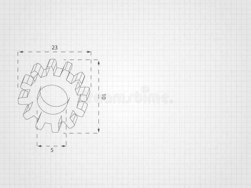
These models can be used in both virtual and actual mechanical assemblies that you design an build using the GEARS-IDS kit. They are full size diagrams of 1 DP 254 mod hobbed gear teeth. All dimensions from your design.
Spur gears or straight-cut gears are the simplest types of gear. In this video show how to draw pinion gear of cctv camera base by used commands C circle enter specify center point D diameter enter 225mm PL pol. Computer-aided design CAD and computer-aided manufacturing CAM are a pair of often interdependent industrial computer applications that have greatly influenced the chain of processes between the initial design and the final realization of a product.
Gears in SVG are measured in pixels which is the value multiplied with the scale Pixel per Unit as it is displayed on the right side. CAD Drawings Search our library of CAD drawings. Products Mounted Bearings Enclosed Gearing Couplings Conveyor Components Bushings Hubs Collars Belted Drives.
And save the note with name Gear Specification. Rack and pinion Module 1 spur gear Z20 steel 8mm hole. You can exchange useful blocks and symbols with other CAD and BIM users.
You can go ahead a use the HATCH command at the end of the design nonetheless the more important in this exercise is to use a little bit of thinking and all techniques we have learned to get the curve right. Dodge Industrial Global Headquarters 1061 Holland Road Simpsonville SC 29681 USA. With the number of teeth equal to 18 - the minimum number to not have geometric undercut effects.
But before make a gear drawing you have to fill custom properties in advance. Ad Download an engineers guide to CAD and the renaissance of product design. Though the teeth are not straight-sided but usually of special form to achieve a constant drive ratio mainly involute but less commonly cycloidal the edge of each tooth is straight and aligned parallel to the axis of rotation.
Spur Gear Tooth Project Description Create a solid model and a working drawing of the 24 pitch gears specified below. The gear is being built. The Computer-Aided Design CAD files and all associated content posted to this website are created uploaded managed and owned by third party users.
In other words at 0 90 180 or 270 degrees. In this video we showcase the drawing a gear with the TurboCAD Gear Tool and then extruding the drawing into a 3D Object i. Each CAD and any associated text image or data is in no way sponsored by or affiliated with any company organization or real-world item product or good it may purport to portray.
The figure on the left is an. The gear has a face-width of 10 mm and a 50 Nm static torque is applied. Today we have this bent pipe joint in 2D to draw as an exercise in AutoCAD.
Below are some samples. 1 Draw a line from the circle center 00 to the base circle perpendicular to your grid. See popular blocks and top brands.
Gear Generator is unitless. SolidWorks OnShape and Solid Edge can load each others part and assembly files but not drawing files without loss of assembly data. They consist of a cylinder or disk with teeth projecting radially.
Module 006 25 teeth thickness 10 mm bore Ø0 mm - NF E 23-011. 50 CAD Practice Drawings Although the drawings of this eBook are made with AutoCAD software still it is not solely eBook contains 30 2D practice drawings and 20 3D practice drawings. Please select 3D XML 3MF Acis 63 Alibre Design AMF Animated GIF AutoCAD DWG - 2D AutoCAD DWG - 3D AutoCAD MEP BMP BricsCAD DWG - 2D BricsCAD DWG - 3D CATIA V4 CATIA V5 COLLADA Creo.
However a conversion will take place and you cant just switch. How to Draw Involute Gear Teeth Using formulas presented in Earle Buckinghams 1950 Edition of Analytical Mechanics of Gears see references we have calculated Cartesian X-Y coordinates for 14½ and 20 Full Depth gear teeth and a 30 involute spline. Gear 96102 views - Mechanical Engineering A gear or cogwheel is a rotating machine part having cut teeth or cogs which mesh with another toothed part to transmit torque.
A second option would be to use a custom lisp routine that draws 2D gears input the required data let the routine draw the complete gear take what you need and erase the remainder. Many would add to this duo a third technology computer-aided engineering CAE. We keep adding The drawings here are intended to be used as a practice material and to help you apply CAD tools on some real-life drawings.
DXF opened in AutoCAD will have the same value for DP as it is set above. Gears almost always produce a change in torque creating a mechanical advantage through their. Tooth forms in models and drawings are for representation only and should not be used for manufacturing purposes.

Force Analysis Of Broken Tooth Of Large Helical Gear Of Loader Drive Axle Zhy Gear
![]()
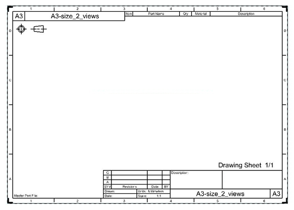
Design Task Single Stage Transmission 2d Drawing 20 And 3d Cad Model Download Scientific Diagram

A Spur Gears Geometry Roymech 2009 B Helical Gear Geometry Download Scientific Diagram

The Parameters Of The Spur Gear Pair Having Normal Straight Teeth Download Scientific Diagram

Parameters Of The Spur Gear Pair Having Modifi Ed Straight Teeth Download Scientific Diagram
![]()
Design Task Single Stage Transmission 2d Drawing 20 And 3d Cad Model Download Scientific Diagram
Why Does Y Autocad Drawing File Appear As Not Valid How Can I Fix This Quora

What Are Cad Tools Quora

Bevel Gear Stock Illustrations 170 Bevel Gear Stock Illustrations Vectors Clipart Dreamstime

Add Dimensions To An Assembly Autodesk Community

Geometric Defects Including A Chipped Tooth Of Gear A And B Download Scientific Diagram
Gear Ratio Stock Illustrations 192 Gear Ratio Stock Illustrations Vectors Clipart Dreamstime
Can T Remove Row From Revison Block Autodesk Community

Pin On Fenetre

Musica Blueprints Blueprints Blueprint Art Technical Drawing